I’ve been pretty quiet over the past week. This is primarily because my day job has kept me busier than I’d like, compounded by the fact that I’ve come down with a cold. But I shall persevere and forge on ahead. The hardware is done, and I’m currently working on the software. But, how exactly does it work? That’s what I hope to show in this post.
Recording data on a cassette tape is actually very simple, at least the way the Apple II does it. The output signal from the computer to the cassette recorder is just a square wave, varying between TTL low and high logic values (about 0V and +5V). The Apple II drives the signal from a 74LS74, and the SYM-I drives it from a 74LS145. Just about anything could drive it, the input impedance to the cassette is about 4k?, it requires very little current.
The width of the cycles in the square wave determine the values being stored. To write a “0”, one full cycle of a 2,000 Hz signal is recorded (low for 250 µs, then high for 250 µs). To write a “1”, one full cycle of a 1,000 Hz signal is recorded (low for 500 µs, high for 500 µs). Here’s a diagram to show what I mean.
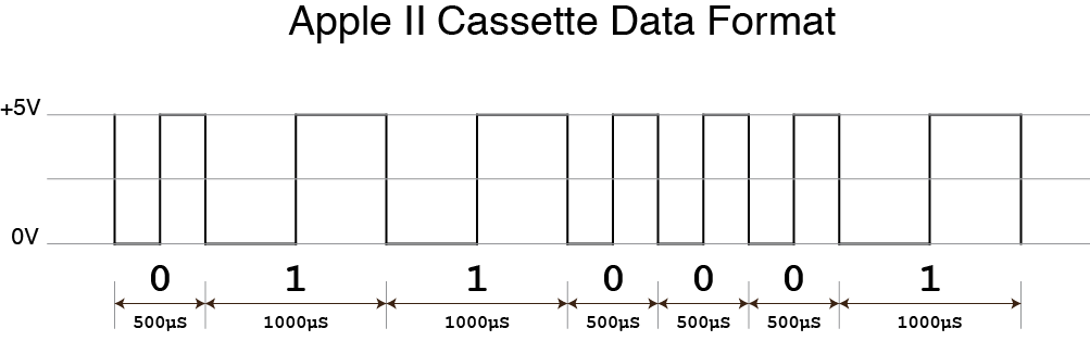
Of course there’s more than just bits on the tape. A full file on tape starts with a header (10 seconds of a 770 Hz square wave), a “Sync” bit indicating the start of data (a single 2500 Hz cycle, 400 µs wide), then the data itself. The last byte of the data is a checksum byte. See, not very complex!
So, now that we know what’s on the tape, how do we write code to read it and write it? Here’s the algorithm, in a slightly condensed form.
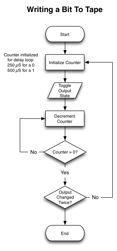
To write a single bit of data to the tape, we need to flip the output state from whatever it currently is, to the opposite (say, from high to low). Then, using a calibrated delay loop, wait until either 250 µs has passed if writing a “0”, or 500 µs if writing a “1”. We do this one more time, this time flipping from low back to high. At the end of the second trip through the delay loop, the bit has been fully written.
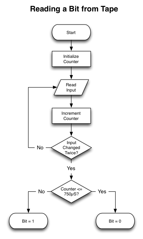
Reading data that’s already been written is similar. The state of an input line coming in from the cassette is monitored in a polling loop (remember, it’s going through a comparator that turns the messy, degraded cassette signal into a nice clean square wave). Each time through the polling loop, a counter is incremented, and we keep looping until we see that the input has changed twice. When that happens, we compare our counter with a known value to see whether we just read a “0” or a “1”
It’s not a difficult problem, but getting the delay loops just right is important. I hope I’ll have some more concrete results to show by next week. We’re closing in on the 15th, so I only have half a month to get everything working. But I’m not worried… yet!
Comments